Euro Blinker Wiring Write up
-
3X00-Modified

- Administrator
- Posts: 10920
- Joined: Thu Jul 05, 2007 9:18 am
- Location: Brooklyn CT
Euro Blinker Wiring Write up
PM ME if you have more info to add.
Euro tails wiring: The Correct Way.
First things first, understand what you're starting with. Factory Beretta contains 2 circuits at the tail lights for turning, parking light and braking function, Circuit 1 is a low level parking light circuit, it is exactly what it sounds like and only that. Circuit 2 is a brake and turn bright level function, It illuminates the tail light solid or blinking depending on if you're using just the brakes or blinker. Obviously the blinker function dominates here so if the brakes are on and you turn signal is also on, one of your lights WILL be blinking for the turn direction. OK now that I've all made you feel like I think you're dumb, it's on to the complex part
You need to create 3 circuits back there to make this work,
Circuit 1, Parking lights.
Circuit 2, Brake lights.
Circuit 3, Turn signals
Obviously 1 and 2 exist, but 2 are paired up with 3, so you need to separate that into individual functions.
Step 1, REMOVE brake light function to rear tails.
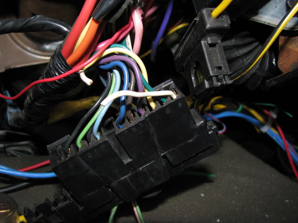
Going under your dash on the driver's side, remove the lower panel and the panel right below the steering column. Find the flat wide connector coming down the column from you blinker switch, you need to snip one wire OR you can pull the pin and cover it if you wish to not cut wires. The wire is a White wire and should be at pin location P. This is the "brake input" to the blinker switch. Once that's removed your tails should now only function as blinker lights.
Step 2, isolate which bulbs perform what function on the tails.
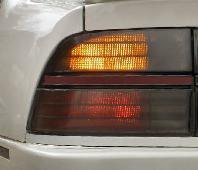
Ok now this is personal preference and can differ from setup to setup, Factory Euro setups have this setup, Upper bulb (amber section) Only blinks and does not come on with parking lights, Lower bulb (Red Section) functions as a parking light and brake light.
To get this setup three things need to be done, remove the parking light wires going to the top bulb, remove the turn light function from the lower bulb, and re-create the brake light only circuit for the lower bulbs.
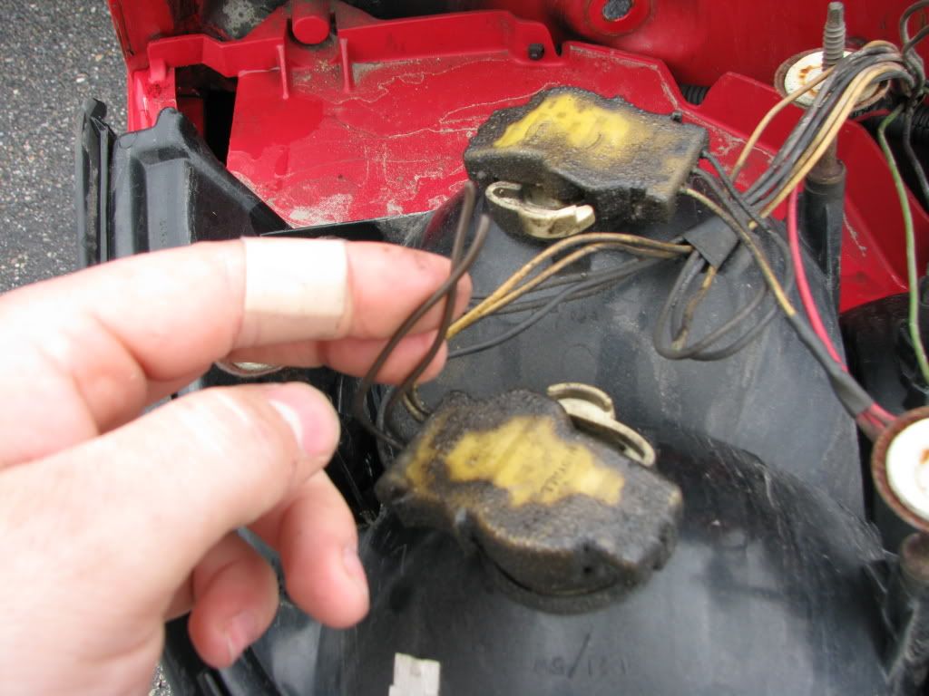
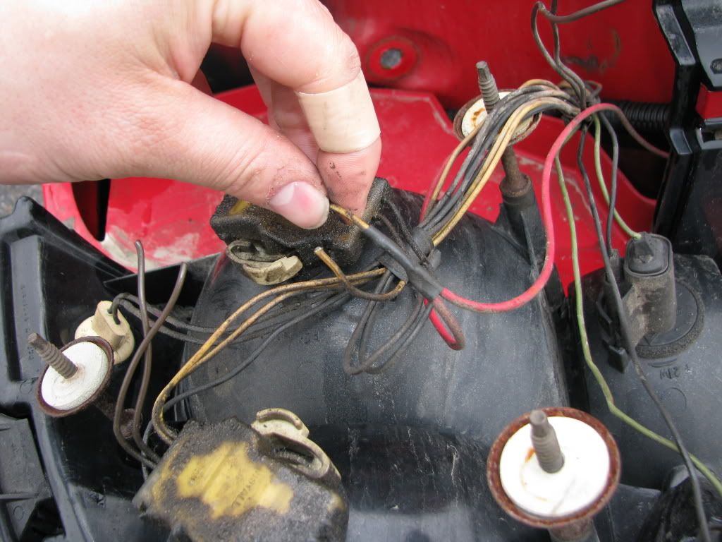
For the top two bulbs, you need to cut the brown wires going to the sockets, this removes the parking light function, If you want you can leave them there, but I've never seen a euro application with the turns lit up as parking lights too. Now when cutting these the sockets are a dual wire connection, so you need to take the wires on the harness side and connect the two back together since that wire was originally using the socket as a junction point, Leaving them separate will break the connection to where it was going (to the lower socket or other side)
Left side
Right side
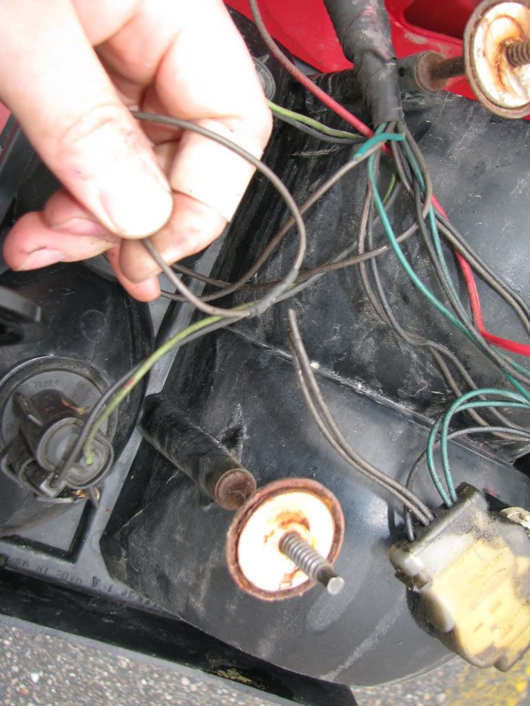
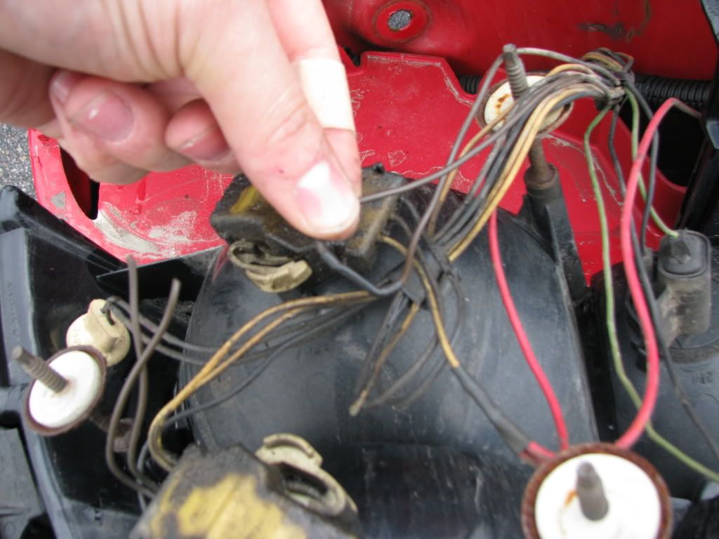
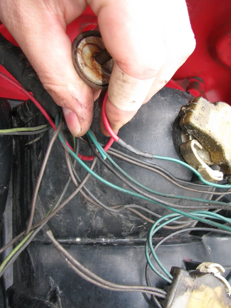
For the lower two bulbs, you need to cut the high level inputs, or the "turn signal input", This will be a Yellow (L) and Green (R) wires, These will not bet the same dual wire setup as above. Leave enough wire off the socket for the next step. Pic below next step shows the original blinking input cut.
Test it. You should have top bulbs acting as blinkers only, not parking, not brake, and the lower bulbs will be functioning as parking only right now.
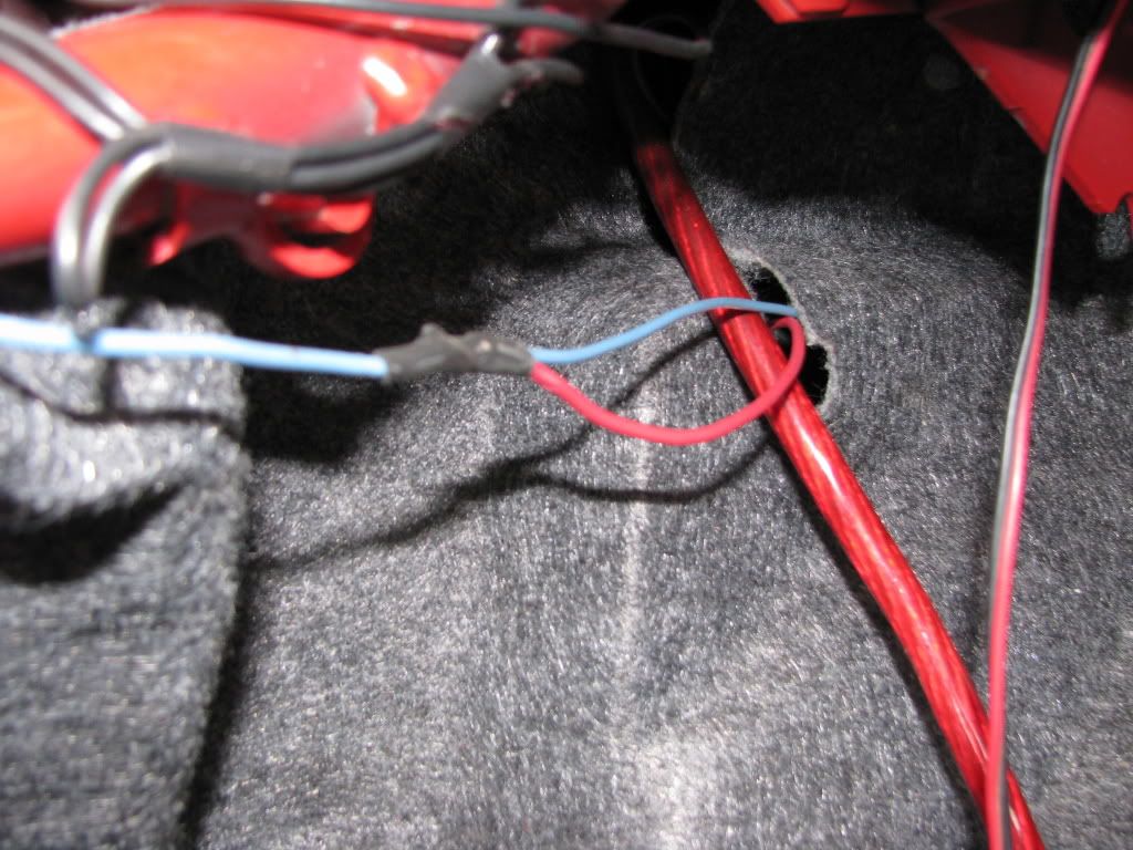
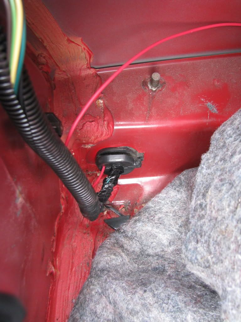
Ok, well you need a brake light circuit right? Guess where that's coming from, that's right the good Ole third brake light. The third brake light is a dedicated circuit directly from the brake pedal; it works regardless of what direction you're tuning so it's just what we need. You need to splice into the wire going to the third brake light, (Blue) and then send that out the bulkhead that's in the left rear quarter area, this goes out to right behind the left corner of the bumper, once you run that wire through that bulk head you are going to run it to both lower tail light bulbs, connecting the two together, so run a wire to the left bulb, and then junction another one there to go to the right bulb, you will be connecting the yellow and green "circuits" together and that's perfectly fine, since you want both bulbs to function the same.
My wire is easily accessable because I have a custom run spoiler light, I'm not sure where the factory wire would be for the spoiler, but even for a standard decklid rear light its right near the speakers.
Left Side
Right Side
Now the hard part Step 3, Find and replace your blinker with an Electronic or HD one.
Factory blinkers require a min of 3 bulbs on the circuit to blink, you now only have 2, so you need to replace that thermal POS blinker for a HD electronic one, the will blink with as little as 2 bulbs, and max of 12 or 24 on the circuit; SO if you burn out a blinker you should STILL be notified by the good ole solid blinker syndrome; I have yet to have that happen to me to prove its right though.
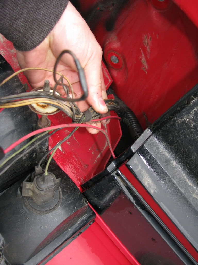
On the pre 96 cars the blinker is NOT on the courtesy module, it's on a standalone tail that's clipped up under the dash, you need to dig for it, Picture below of the electronic one installed on the tail, The 96 cars have it right on the courtesy module, Now I'm not sure but I believe you still need the HD one but it's a slightly different part number, since it's a 3 pin flasher and not a 2 pin one. I'll post Part numbers when I find them, but that flasher is much easier to find and replace. Ask Geoff, He has a 96 module and Euro tails, wired the correct way IIRC.
On a 94-95 car and possibly older ones they are a seperate tail of wiring and its clipped way up above the courtesy module, you need to dig for it...See pic, Its a single pink and double purple wire 2 pin connector, the purple wires go to the same connection obviously.
Once again Test all your lights and make sure your brake lights work and the blinkers also work.
Good luck!
Euro tails wiring: The Correct Way.
First things first, understand what you're starting with. Factory Beretta contains 2 circuits at the tail lights for turning, parking light and braking function, Circuit 1 is a low level parking light circuit, it is exactly what it sounds like and only that. Circuit 2 is a brake and turn bright level function, It illuminates the tail light solid or blinking depending on if you're using just the brakes or blinker. Obviously the blinker function dominates here so if the brakes are on and you turn signal is also on, one of your lights WILL be blinking for the turn direction. OK now that I've all made you feel like I think you're dumb, it's on to the complex part
You need to create 3 circuits back there to make this work,
Circuit 1, Parking lights.
Circuit 2, Brake lights.
Circuit 3, Turn signals
Obviously 1 and 2 exist, but 2 are paired up with 3, so you need to separate that into individual functions.
Step 1, REMOVE brake light function to rear tails.
Going under your dash on the driver's side, remove the lower panel and the panel right below the steering column. Find the flat wide connector coming down the column from you blinker switch, you need to snip one wire OR you can pull the pin and cover it if you wish to not cut wires. The wire is a White wire and should be at pin location P. This is the "brake input" to the blinker switch. Once that's removed your tails should now only function as blinker lights.
Step 2, isolate which bulbs perform what function on the tails.
Ok now this is personal preference and can differ from setup to setup, Factory Euro setups have this setup, Upper bulb (amber section) Only blinks and does not come on with parking lights, Lower bulb (Red Section) functions as a parking light and brake light.
To get this setup three things need to be done, remove the parking light wires going to the top bulb, remove the turn light function from the lower bulb, and re-create the brake light only circuit for the lower bulbs.
For the top two bulbs, you need to cut the brown wires going to the sockets, this removes the parking light function, If you want you can leave them there, but I've never seen a euro application with the turns lit up as parking lights too. Now when cutting these the sockets are a dual wire connection, so you need to take the wires on the harness side and connect the two back together since that wire was originally using the socket as a junction point, Leaving them separate will break the connection to where it was going (to the lower socket or other side)
Left side
Right side
For the lower two bulbs, you need to cut the high level inputs, or the "turn signal input", This will be a Yellow (L) and Green (R) wires, These will not bet the same dual wire setup as above. Leave enough wire off the socket for the next step. Pic below next step shows the original blinking input cut.
Test it. You should have top bulbs acting as blinkers only, not parking, not brake, and the lower bulbs will be functioning as parking only right now.
Ok, well you need a brake light circuit right? Guess where that's coming from, that's right the good Ole third brake light. The third brake light is a dedicated circuit directly from the brake pedal; it works regardless of what direction you're tuning so it's just what we need. You need to splice into the wire going to the third brake light, (Blue) and then send that out the bulkhead that's in the left rear quarter area, this goes out to right behind the left corner of the bumper, once you run that wire through that bulk head you are going to run it to both lower tail light bulbs, connecting the two together, so run a wire to the left bulb, and then junction another one there to go to the right bulb, you will be connecting the yellow and green "circuits" together and that's perfectly fine, since you want both bulbs to function the same.
My wire is easily accessable because I have a custom run spoiler light, I'm not sure where the factory wire would be for the spoiler, but even for a standard decklid rear light its right near the speakers.
Left Side
Right Side
Now the hard part Step 3, Find and replace your blinker with an Electronic or HD one.
Factory blinkers require a min of 3 bulbs on the circuit to blink, you now only have 2, so you need to replace that thermal POS blinker for a HD electronic one, the will blink with as little as 2 bulbs, and max of 12 or 24 on the circuit; SO if you burn out a blinker you should STILL be notified by the good ole solid blinker syndrome; I have yet to have that happen to me to prove its right though.
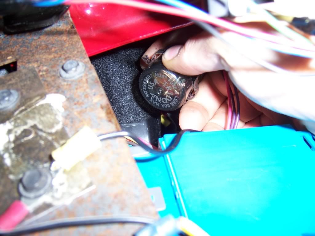
On the pre 96 cars the blinker is NOT on the courtesy module, it's on a standalone tail that's clipped up under the dash, you need to dig for it, Picture below of the electronic one installed on the tail, The 96 cars have it right on the courtesy module, Now I'm not sure but I believe you still need the HD one but it's a slightly different part number, since it's a 3 pin flasher and not a 2 pin one. I'll post Part numbers when I find them, but that flasher is much easier to find and replace. Ask Geoff, He has a 96 module and Euro tails, wired the correct way IIRC.
On a 94-95 car and possibly older ones they are a seperate tail of wiring and its clipped way up above the courtesy module, you need to dig for it...See pic, Its a single pink and double purple wire 2 pin connector, the purple wires go to the same connection obviously.
Once again Test all your lights and make sure your brake lights work and the blinkers also work.
Good luck!

Re: Euro Blinker Wiring Write up
Aww you got a boo boo lol
Good writeup though
Good writeup though

-
el_roy1985
- Registered User
- Posts: 54
- Joined: Sun Jul 12, 2009 12:47 am
- Location: Bismarck, ND
Re: Euro Blinker Wiring Write up
Nice, and I just went through the wiring diagram to figure out how to do this. The only problem was that it didn't help me find the wire I needed to cut. Thanks to your great write-up, I'll know exactly where to find it. 
3400/5 speed, internet Tune, FFP UDP, Billet/poly mounts, ported intake manifolds, WAI, 2.5" mandrel exhaust w/ dp, Borla ProXS, Intrax, KYB, poly front end kid, welded a-arms, strut, shock and sub-frame braces.

Re: Euro Blinker Wiring Write up
Having done it, it is SUPER easy to do. Def get the electronic flasher or it will flash retarded.
-
90GTZHO
- Registered User
- Posts: 1068
- Joined: Sun Nov 02, 2003 11:54 am
- Location: Paulden, AZ
- Contact:
Re: Euro Blinker Wiring Write up
This would be even something us US spec lighted people could do if you wanted. Too bad theres no way to find the amber lenses on their own somewhere 
Geoff
95 Base V6: Current Project; Work In Progress
95 Base V6: Current Project; Work In Progress
-
Puska 35.M
- Registered User
- Posts: 33
- Joined: Sat Jul 21, 2012 12:56 am
- Location: Fulton, Wisconsin, USA
Re: Euro Blinker Wiring Write up
So what, exactly, is the difference if you are wiring a 1996?
-
3X00-Modified
- Administrator
- Posts: 10920
- Joined: Thu Jul 05, 2007 9:18 am
- Location: Brooklyn CT
Re: Euro Blinker Wiring Write up
The blinker relay is on the courtesy module and not on a tail wire just stuffed up there. I think that's the only difference.